The majority of today was dedicated to the assembly of the square bot. After the long arduous task of assembling, and sometimes disassembling and reassembling, the bot was finally completed and i was able to use the remote controller to drive it around the classroom.
Electronics 10 JJMartinez
Thursday, February 14, 2013
1/10/13
Today we started of with switches and were introduced to the numerous types that exist, such as SPST, SPDT, DPDT, and so on. The first project was to arrange two SPDT switches in a way where either switch can turn on or off the light, or LED in this case.
The segment of the handout went into the usage of relays and how they worked. Using a push button to control the relay's internal inductor, we were able to switch on a light, or LED in this case, with the added push button.
The segment of the handout went into the usage of relays and how they worked. Using a push button to control the relay's internal inductor, we were able to switch on a light, or LED in this case, with the added push button.
1/9/13
The next project was to further demonstrate the relationship between brightness and resistance by using a potentiometer to adjust the LED's brightness.
1/23/13
The next demonstration of the micro-controlled driven toy motor was simply the motor moving in one direction for an amount of time, and then moving in the reverse direction for the same amount of time.
Wednesday, January 23, 2013
1/22/13
Starting off from where i ended last week, i began the arduous task of reconstructing my toy after testing the motors. The toy was rebuilt with protruding wires, which will allow me access to the motors from the outside.
After that, i was finally able to start the motor driving handout. The first circuit was a demonstration of using a transistor to control a large current load with the microprocessor.
And shortly after completing that circuit, i was able to start and complete the next circuit in the handout. This circuit was demonstration of a Darlington Pair configuration used to drive a current-heavy load with a high level of resistance on the base of the first transistor.
Saturday, January 19, 2013
1/8/13 Building my 5v power supply
The first project of the night was some simple soldering of various resistors and capacitors onto small circuit boards.
After I mastered my circuit board soldering skills, the next task was to solder the ends of numerous, small lengths of wires together in a sort-of ring-like pattern.
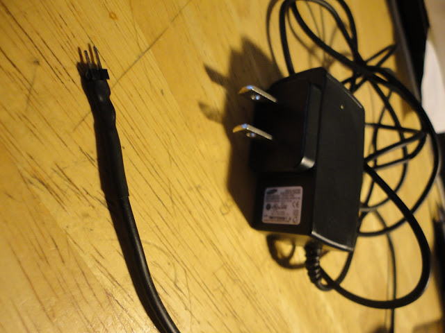
When i was able to finish the ring project, i was finally able to move on to the final project of the night, which was my 5-volt power supply that i was to use for the rest of the semester.
Subscribe to:
Posts (Atom)


